

Wireless High and Low Voltage Phase Checking Instrument HYEC-10
HYEC-10, is an intelligent phase checking meter. Contact phase checking method and non-contact phase checking method are uesd in the meter. The non-contact phase checking method avoids direct contact with the high voltage wire, so it is safer! The phase checking instrument can also function as high-voltage electroscope, high-pressure phase meter and high-pressure phase sequence meter, which can be used for testing electricity, phase sequence test, transformer group judgment and so on.
 Datasheet
 Video
Video Contact Us
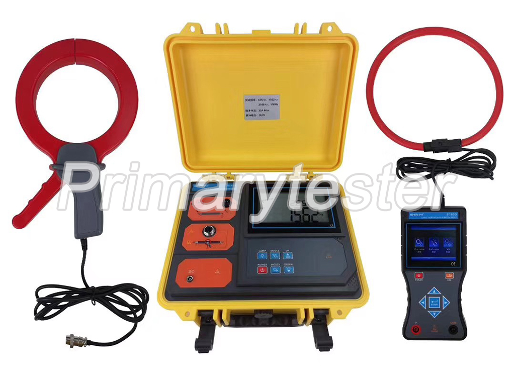
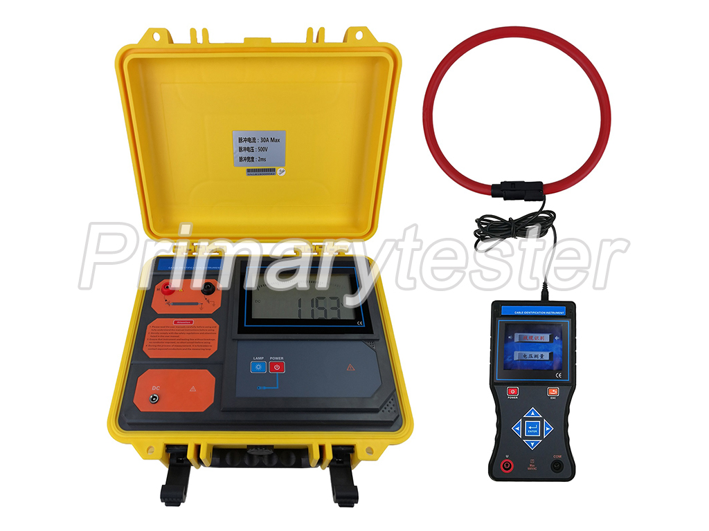
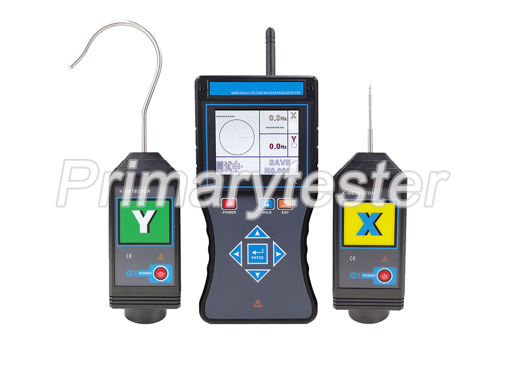
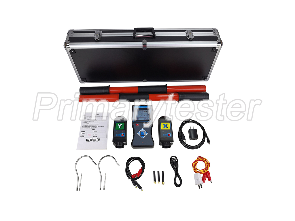
1. The tester contains wireless receiver, XY detector, retractable insulated rod and other components.
2. The receiver contains a 3.5-inch true color LCD screen, which can show the phase checking results, phase, frequency, and vector diagram instructions at the same time, which makes it clear and intuitive.
3. The phase checking distance on the open ground is up to 1600m far, full intelligent phase checking of the voltage line covers the voltage of 10V ~ 550kV, in which the bare wire voltage of 35kV and below can be directly conducted with contact phase checking, and the bare wire voltage of over 35kV can be directly conducted with non-contact phase checking.
4. Noncontact phase checking is to make the detector closer to the wire under test, and when the electric signal is inducted, the phase checking will be completed. This method avoids direct contact with the high voltage wire. It is safer and more convenient.
Function | Wireless high and low voltage voice phase checking; frequency, phase, phase sequence, electroscope test |
Power source | DC 3.7V chargeable lithium battery, USB charging portal, working continuously for 10h |
Transmission method | 315MHz and 433MHz wireless transmission |
Phase checking distance | About 1600m, the distance of phase checking divided into long distance mode (about 1600m) and short distance mode (about 150m) which are switchable (details shown in Basic operations) |
Display mode | 3.5-inch true color LCD display |
Measurement range | Phase checking voltage level: AC 10V~550kV |
Phase: 0.0°~360.0° | |
Frequency: 45Hz~75Hz | |
Resolution | 0.1°; 0.1Hz |
Precision | Phase: ≤±10° (23℃±5℃, below 80%RH) |
Frequency: ≤±2Hz (23℃±5℃, below 80%RH) | |
Phase judge | In phase:-30°~30°; out of phase: 90°~150° and 210°~270° |
Voice function | Voice such as in phase, out of phase, X signal normal, Y signal normal, etc. |
Size of insulation rod | About 5m long after extended; about 1m long after drawn back (5 nodes) |
Data storage | 9999 sets |
Phase | Contact phase checking: When the bare wire voltage is less than 35kV, or less than 110kV with a safety insulation sheath wire, adopt contact phase checking. (operating with an insulation rod) |
Noncontact phase checking: When the bare wire voltage is more than 35kV, or more than 110kV with a safety insulation sheath wire, adopt noncontact phase checking. (operating with an insulation rod) | |
Electric indicator | Detector sends out buzz like "beep - beep -beep" |
Gear shift | Automatic gear shifting |
Sample frequency | 2 times/s |
Instrument size | Detector: length width and thickness 145mm×60mm×48mm |
Receiver: length width and thickness 250mm×100mm×40mm | |
Backlight | Press Up or Down Arrow button to adjust the backlight luminance |
Induction | Detector automatically increases or decreases the signal amplification factor according to the intensity of the electric field, facilitating the phase checking in a place of intensive lines |
Data | Press HOLD button under testing mode to maintain the data, and then press HOLD button again to cancel the maintenance |
Exit function | Press ESC button to exit from current interface and return to the upper directory |
Data | Press ENTER to determine data reference mode, and press Arrow button to refer to all the stored data |
No-signal indicator | When the receiver does not receive the transmission signal, it dynamically displays “----” symbol |
Automatic shutdown | About 15mins after startup, the instrument will be automatically shut down to reduce battery consumption |
Battery voltage | When the battery voltage is lower than 3.2V: |
Rated | Detector: 35mA max; Receiver: 300mA max |
Instrument | Detector: 205g (including battery) |
Receiver: 395g (including battery) | |
Insulation rod: 1.45kg | |
Total mass: 9.8kg (including instrument box) | |
Working | -10℃~40℃; below 80%Rh |
Storage humidity and temperature | -10℃~60℃; below 70%Rh |
Interference | No extra strong electromagnetic field; no interference from other 433MHz or 315MHz signals |
Insulation intensity | Insulation rod: AC 110kV/rms (between both ends after 5 nodes of insulation rod are totally extended) |
Detector: 2000V/rms (between both ends of outer shell) | |
Receiver: 2000V/rms (between both ends of outer shell) | |
Structure | Anti-dripping Type II and IP63 |
Safety rules of satisfaction | Satisfy GB13398-92, GB311.1-311.6-8, 3DL408-91 standards and the newly promulgated power industry standard of the state General technical condition DL/T971-2005 for 1kV ~ 35kV portable phase checking device for live work |
Satisfy IEC61481-A2: 2004; IEC 61243-1 ed.2: 2003 standards |
-

Pre-sale service commitments
-

Sale service commitments
-

Sale service commitments